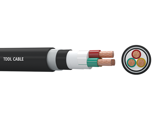
N2XRY (YJV32) 0.6-1kV

N2XRY (YJV32) 0.6-1kV

These power cables are used for electricity supply in low voltage installation systems. They are well adapted to underground use in industrial applications with an additional mechanical protection. They are suitable for laying Indoor, tunnel, cable trench, shaft or buried laying. The cable can withstand mechanical external forces and a certain tensile force, it widely used in transformer stations, electric power plants and industrial plants.
Quote Now
Share :
Application
These power cables are used for electricity supply in low voltage installation systems. They are well adapted to underground use in industrial applications with an additional mechanical protection. They are suitable for laying Indoor, tunnel, cable trench, shaft or buried laying. The cable can withstand mechanical external forces and a certain tensile force, it widely used in transformer stations, electric power plants and industrial plants.

Construction
● Conductor: Copper, class 1 or class 2, solid or stranded, circular or circular compacted conductors   
● Insulation: Cross-linked polyethylene XLPE
● Filler: Non-hygroscopic material
● Binder: Non-hygroscopic material
● Inner sheath: Polyvinyl chloride PVC
● Armour: Steel wire
● Binder: Non-hygroscopic material
● Outer sheath: Polyvinyl chloride PVC

Chaircteritics
Good electrical and mechanical properties. Cross-linked polyethylene insulation allows greater power capacity under any operating condition, minimum dielectric losses, high insulation resistance. The PVC outer sheath allows an adequate resistance to oil and abrasion. 

Specification
IEC 60228 Conductors of Insulate Cables 
IEC 60502-1 Power Cables with Extruded Insulation and Their Accessories for Rated Voltages from 1kV(Um=1.2kV) up to 30kV(Um=36kV) - Part 1: Cables for Rated Voltages of 1kV (Um=1.2kV) and 3kV(Um=3.6kV)
High reliability
Super high pressure
Less maintenance
Technical Parameter
No. of Cores and Nominal Cross Section Min. Number of Wires Nominal Insulation Thickness Nominal
Steel Wire Diameter
Nominal
Sheath Thickness
Approx.
Overall Diameter
Approx. Weight Max. D.C. Resistance of Conductor
at 20℃
No. × mm² No. mm mm mm mm kg/km Ω/km
2×1.5 1 0.7 0.8 1.8 13.3 300 12.1
2×2.5 1 0.7 0.8 1.8 14.1 343 7.41
2×4 1 0.7 0.8 1.8 15.1 404 4.61
2×6 1 0.7 0.8 1.8 16.1 476 3.08
2×10 6 0.7 1.25 1.8 19.5 763 1.83
2×16 6 0.7 1.25 1.8 21.1 942 1.15
2×25 6 0.9 1.6 1.8 25.0 1384 0.727
2×35 6 0.9 1.6 1.8 27.0 1668 0.524
2×50 6 1.0 1.6 1.8 30.0 2061 0.387
2×70 12 1.1 1.6 2.0 33.8 2628 0.268
2×95 15 1.1 2.0 2.1 39.1 3649 0.193
2×120 18 1.2 2.0 2.2 42.5 4334 0.153
2×150 18 1.4 2.0 2.3 46.5 5134 0.124
2×185 30 1.6 2.5 2.5 52.3 6658 0.0991
2×240 34 1.7 2.5 2.7 57.7 8140 0.0754
2×300 34 1.8 2.5 2.8 63.1 9754 0.0601
2×400 53 2.0 2.5 3.1 70.1 12015 0.0470
3×1.5 1 0.7 0.8 1.8 13.8 331 12.1
3×2.5 1 0.7 0.8 1.8 14.6 384 7.41
3×4 1 0.7 0.8 1.8 15.6 460 4.61
3×6 1 0.7 0.8 1.8 16.7 552 3.08
3×10 6 0.7 1.25 1.8 20.4 889 1.83
3×16 6 0.7 1.25 1.8 22.1 1133 1.15
3×25 6 0.9 1.6 1.8 26.2 1680 0.727
3X35 6 0.9 1.6 1.8 28.4 2051 0.524
3×50 6 1.0 1.6 1.9 31.8 2572 0.387
3×70 12 1.1 2.0 2.0 37.2 3637 0.268
No. of Cores and Nominal Cross Section Min. Number of Wires Nominal Insulation Thickness Nominal
Steel Wire Diameter
Nominal
Sheath Thickness
Approx.
Overall Diameter
Approx. Weight Max. D.C. Resistance of Conductor
at 20℃
No. × mm² No. mm mm mm mm kg/km Ω/km
3×95 15 1.1 2.0 2.2 41.5 4626 0.193
3×120 18 1.2 2.0 2.3 45.2 5565 0.153
3×150 18 1.4 2.5 2.5 51.1 7121 0.124
3×185 30 1.6 2.5 2.6 55.6 8522 0.0991
3×240 34 1.7 2.5 2.8 61.8 10612 0.0754
3×300 34 1.8 2.5 3.0 67.4 12798 0.0601
3×400 53 2.0 2.5 3.2 74.7 15826 0.0470
4×1.5 1 0.7 0.8 1.8 14.5 372 12.1
4×2.5 1 0.7 0.8 1.8 15.4 435 7.41
4×4 1 0.7 0.8 1.8 16.6 531 4.61
4×6 1 0.7 1.25 1.8 18.7 765 3.08
4×10 6 0.7 1.25 1.8 21.8 1049 1.83
4×16 6 0.7 1.6 1.8 24.4 1473 1.15
4×25 6 0.9 1.6 1.8 28.3 2017 0.727
4×35 6 0.9 1.6 1.9 30.9 2495 0.524
4×50 6 1.0 1.6 2.0 34.7 3157 0.387
4×70 12 1.1 2.0 2.2 40.7 4493 0.268
4×95 15 1.1 2.0 2.3 45.3 5742 0.193
4×120 18 1.2 2.5 2.5 51.0 7417 0.153
4×150 18 1.4 2.5 2.6 55.8 8806 0.124
4×185 30 1.6 2.5 2.8 61.4 10739 0.0991
4×240 34 1.7 2.5 3.0 67.9 13321 0.0754
4×300 34 1.8 2.5 3.2 74.1 16097 0.0601
4×400 53 2.0 3.15 3.5 84.1 21074 0.0470
5×1.5 1 0.7 0.8 1.8 15.3 414 12.1
5×2.5 1 0.7 0.8 1.8 16.3 492 7.41
5×4 1 0.7 1.25 1.8 18.5 726 4.61
5×6 1 0.7 1.25 1.8 19.9 874 3.08
5×10 6 0.7 1.25 1.8 23.3 1214 1.83
5×16 6 0.7 1.6 1.8 26.1 1723 1.15
No. of Cores and Nominal Cross Section Min. Number of Wires Nominal Insulation Thickness Nominal
Steel Wire Diameter
Nominal
Sheath Thickness
Approx.
Overall Diameter
Approx. Weight Max. D.C. Resistance of Conductor
at 20℃
No. × mm² No. mm mm mm mm kg/km Ω/km
5×25 6 0.9 1.6 1.8 30.5 2362 0.727
5×35 6 0.9 1.6 1.9 33.4 2953 0.524
5×50 6 1.0 2.0 2.1 39.3 4090 0.387
5×70 12 1.1 2.0 2.3 44.3 5352 0.268
5×95 15 1.1 2.5 2.5 51.0 7379 0.193
5×120 18 1.2 2.5 2.6 55.5 8856 0.153
5×150 18 1.4 2.5 2.8 61.4 10690 0.124
5×185 30 1.6 2.5 3.0 67.2 12917 0.0991
5×240 34 1.7 2.5 3.2 74.4 16133 0.0754
5×300 34 1.8 3.15 3.4 82.9 20582 0.0601
5×400 53 2.0 3.15 3.8 92.4 25587 0.0470
3×2.5+1×1.5 1/1 0.7/0.7 0.8 1.8 15.2 418 7.41/12.1
3×4+1×2.5 1/1 0.7/0.7 0.8 1.8 16.3 508 4.61/7.41
3×6+1×4 1/1 0.7/0.7 1.25 1.8 18.4 740 3.08/4.61
3×10+1×6 6/1 0.7/0.7 1.25 1.8 21.0 977 1.83/3.08
3×16+1×10 6/6 0.7/0.7 1.25 1.8 23.2 1268 1.15/1.83
3×25+1×16 6/6 0.9/0.7 1.6 1.8 27.3 1879 0.727/1.15
3×35+1×16 6/6 0.9/0.7 1.6 1.8 29.1 2225 0.524/1.15
3×50+1×25 6/6 1.0/0.9 1.6 1.9 33.0 2856 0.387/0.727
3×70+1×35 12/6 1.1/0.9 2.0 2.1 38.6 4045 0.268/0.524
3×95+1×50 15/6 1.1/1.0 2.0 2.2 43.0 5162 0.193/0.387
3×120+1×70 18/12 1.2/1.1 2.0 2.4 47.3 6325 0.153/0.268
3×150+1×70 18/12 1.4/1.1 2.5 2.5 52.4 7841 0.124/0.268
3×185+1×95 30/15 1.6/1.1 2.5 2.7 57.5 9512 0.0991/0.193
3×240+1×120 34/18 1.7/1.2 2.5 2.9 63.8 11870 0.0754/0.153
3×300+1×150 34/18 1.8/1.4 2.5 3.0 69.5 14254 0.0601/0.124
3×400+1×185 53/30 2.0/1.6 3.15 3.3 78.8 18672 0.0470/0.0991
3×2.5+2×1.5 1/1 0.7/0.7 0.8 1.8 15.9 459 7.41/12.1
3×4+2×2.5 1/1 0.7/0.7 1.25 1.8 18.0 678 4.61/7.41
3×6+2×4 1/1 0.7/0.7 1.25 1.8 19.3 817 3.08/4.61
No. of Cores and Nominal Cross Section Min. Number of Wires Nominal Insulation Thickness Nominal
Steel Wire Diameter
Nominal
Sheath Thickness
Approx.
Overall Diameter
Approx. Weight Max. D.C. Resistance of Conductor
at 20℃
No. × mm² No. mm mm mm mm kg/km Ω/km
3×10+2×6 6/1 0.7/0.7 1.25 1.8 21.9 1073 1.83/3.08
3×16+2×10 6/6 0.7/0.7 1.6 1.8 25.3 1565 1.15/1.83
3×25+2×16 6/6 0.9/0.7 1.6 1.8 28.7 2106 0.727/1.15
3×35+2×16 6/6 0.9/0.7 1.6 1.8 30.4 2448 0.524/1.15
3×50+2×25 6/6 1.0/0.9 2.0 2.0 36.4 3499 0.387/0.727
3×70+2×35 12/6 1.1/0.9 2.0 2.1 40.4 4487 0.268/0.524
3×95+2×50 15/6 1.1/1.0 2.0 2.3 45.4 5750 0.193/0.387
3×120+2×70 18/12 1.2/1.1 2.5 2.5 51.6 7638 0.153/0.268
3×150+2×70 18/12 1.4/1.1 2.5 2.6 54.9 8637 0.124/0.268
3×185+2×95 30/15 1.6/1.1 2.5 2.8 60.9 10700 0.0991/0.193
3×240+2×120 34/18 1.7/1.2 2.5 3.0 67.0 13208 0.0754/0.153
3×300+2×150 34/18 1.8/1.4 2.5 3.2 73.4 15945 0.0601/0.124
3×400+2×185 53/30 2.0/1.6 3.15 3.5 83.0 20775 0.0470/0.0991
4×2.5+1×1.5 1/1 0.7/0.7 0.8 1.8 16.1 476 7.41/12.1
4×4+1×2.5 1/1 0.7/0.7 1.25 1.8 18.2 697 4.61/7.41
4×6+1×4 1/1 0.7/0.7 1.25 1.8 19.6 850 3.08/4.61
4×10+1×6 6/1 0.7/0.7 1.25 1.8 22.6 1143 1.83/3.08
4×16+1×10 6/6 0.7/0.7 1.6 1.8 25.7 1644 1.15/1.83
4×25+1×16 6/6 0.9/0.7 1.6 1.8 29.6 2226 0.727/1.15
4×35+1×16 6/6 0.9/0.7 1.6 1.9 32.0 2698 0.524/1.15
4×50+1×25 6/6 1.0/0.9 2.0 2.1 38.0 3802 0.387/0.727
4×70+1×35 12/6 1.1/0.9 2.0 2.2 42.4 4931 0.268/0.524
4×95+1×50 15/6 1.1/1.0 2.0 2.4 47.5 6325 0.193/0.387
4×120+1×70 18/12 1.2/1.1 2.5 2.5 53.4 8233 0.153/0.268
4×150+1×70 18/12 1.4/1.1 2.5 2.7 57.9 9632 0.124/0.268
4×185+1×95 30/15 1.6/1.1 2.5 2.9 64.0 11824 0.0991/0.193
4×240+1×120 34/18 1.7/1.2 2.5 3.1 70.7 14645 0.0754/0.153
4×300+1×150 34/18 1.8/1.4 3.15 3.3 79.0 18714 0.0601/0.124
4×400+1×185 53/30 2.0/1.6 3.15 3.6 87.6 23183 0.0470/0.0991
                  No. of cores and nominal cross section Phase Messenger Approx. overall diameter Approx. weight Max. DC resistance ofconductor
at 20℃
Min.
Number
Ofwires
Nominal insulation thickness Nominal   AL/PET tape thickness Nominal
sheath thickness
Conductor Nominal insulation thickness
mm² No. mm mm mm No./mm mm mm kg/km Ω/km
3×1×50+1×50 6 4.5 0.20 2.0 7/3.0 1.2 55.1 2220 0.387
3×1×70+1×50 12 4.5 0.20 2.0 7/3.0 1.2 58.8 2528 0.268
3×1×95+1×50 15 4.5 0.20 2.0 7/3.0 1.2 62.6 2888 0.193
3×1×120+1×50 15 4.5 0.20 2.0 7/3.0 1.2 65.2 3181 0.153
3×1×150+1×50 15 4.5 0.20 2.0 7/3.0 1.2 68.5 3520 0.124
3×1×185+1×50 30 4.5 0.20 2.0 7/3.0 1.2 72.1 3956 0.0991
3×1×240+1×50 30 4.5 0.20 2.1 7/3.0 1.2 77.5 4648 0.0754
3×1×300+1×50 30 4.5 0.20 2.1 7/3.0 1.2 82.3 5329 0.0601
3×1×400+1×50 53 4.5 0.20 2.2 7/3.0 1.2 88.6 6292 0.0470
3×1×500+1×50 53 4.5 0.20 2.3 7/3.0 1.2 96.6 7509 0.0366
3×1×630+1×50 53 4.5 0.20 2.4 7/3.0 1.2 105.0 9027 0.0283


For more product details, please download our PDF files.
PDF Download
Online message
Subject *
Name
Email *
City
Message *
I agree to the Privacy Policy and accept these conditions